第1步:我們需要什么
電子產品:
1。 2 x 22M歐姆+電阻器 (電阻值越大,傳感器反應越遠,我個人使用22M歐姆,獲得可用數據的最小值為10M歐姆)
2。 3x 330歐姆電阻
3. 電線
4。 乙 readboard
5 即可。 電路板(我的銅條連續不斷)
6。 多個常見的陰極RGB Leds (我使用8,但你可以或多或少取決于你想要多少光)
7。 鋁箔
8。 Cling wrap
9。 Arduino Uno
10。 錄像帶
案例:
1。 Wood 我使用的是50 x 50 x 1.8 CM MDF(你可以使用任何東西。這取決于你想要的效果和你可以使用的工具)
的 2。 亞克力有機玻璃我使用50 x 50 x 0.3 CM(或任何其他透明/半透明材料,如宣紙)
3。 砂紙(細砂紙)
4. 木膠
5. 膠合板(可選)
6. 丙烯酸膠
工具:
剝線器
烙鐵+錫
Stanley刀
鉆
鋸(我用過臺鋸)
第2步:原型設計:
現在我們有了一切,我們可以開始制作原型,看看它是如何工作的:
準備工作:
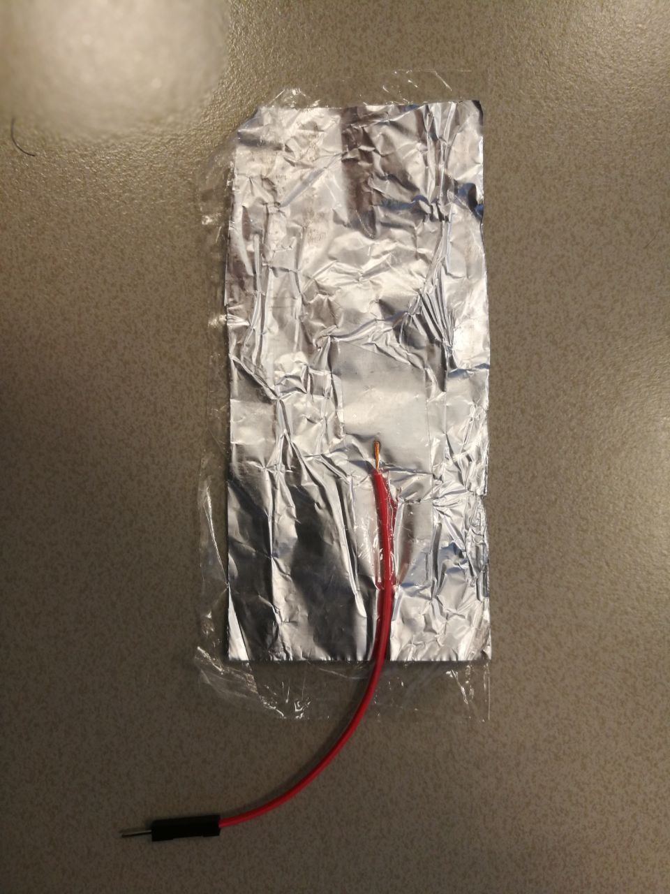
從鋁箔上切下4個矩形(我的大約10厘米乘5厘米),將它們用保鮮膜包裹起來,以防止它們直接接觸并將電線粘在鋁箔上。我只是在箔上剝了一個剝離的末端(只要它們保持接觸)。
為了確保鋁是安全絕緣的,我用保鮮膜包好并在紙之間熨燙(只需幾秒鐘)所以它沒有完全融化。)
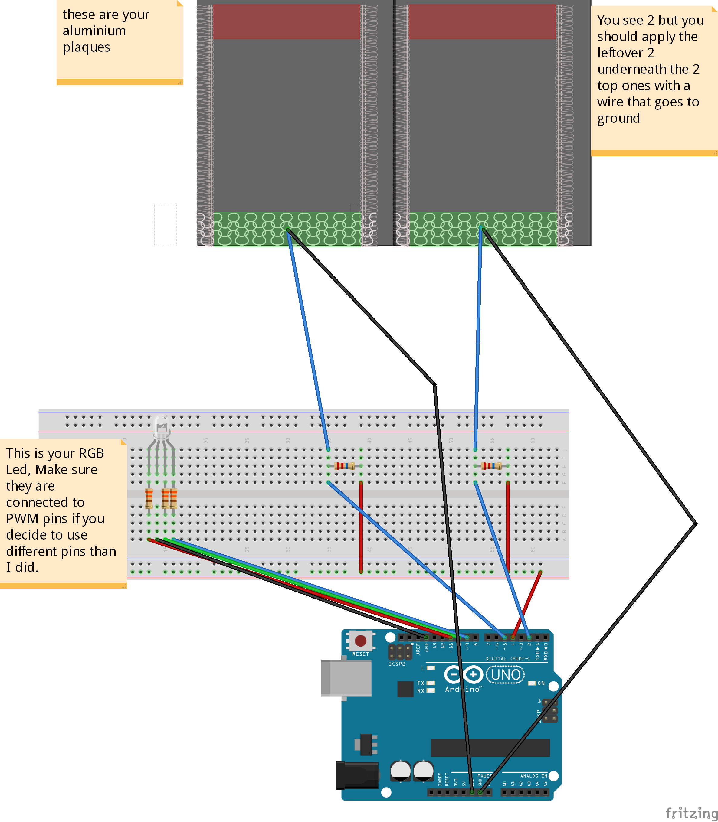
然后設置電路,如圖所示。
引腳4用作兩個傳感器的發送引腳,而接收引腳是引腳2和5.您可以使用多個發送引腳,但由于它們不是完全同步而導致故障。
在將所有內容焊接在一起之前使用此設置進行調試,以確保一切真正按預期工作。
步驟3:代碼:
現在我們擁有一切,我們可以開始調試傳感器了。
要使用我的代碼,你應該從Arduino下載電容感應庫并按照參考頁面給出的指示進行安裝:點擊我
代碼:(我不是非常適合編碼,所以如果你知道如何更好地做,請做)
#include //import the code library
CapacitiveSensor cs_4_2 = CapacitiveSensor(4,2); //Send pin = 4, receive are 2 and 5
CapacitiveSensor cs_4_5 = CapacitiveSensor(4,5);
const int redPin = 11;
const int greenPin = 10;
const int bluePin = 9;
const int numIndexR = 10; // array size
const int numIndexG = 10;
int colorR = 0;
int colorG = 0;
float colorB = 0;
int indexR [numIndexR];
int posIndexR = 0;
long totalR = 0; //it needs to be a long because the total of my array was to big for an integer.
int averageR = 0;
int indexG [numIndexG];
int posIndexG = 0;
long totalG = 0;
int averageG = 0;
void setup()
{
pinMode(redPin, OUTPUT);
pinMode(greenPin, OUTPUT);
pinMode(bluePin, OUTPUT);
for (int thisIndexR = 0; thisIndexR 《 numIndexR; thisIndexR++) { //sets the array to 0
indexR [thisIndexR] = 0;
}
for (int thisIndexG = 0; thisIndexG 《 numIndexG; thisIndexG++) {
indexG [thisIndexG] = 0;
}
colorR = 255; //turns on all leds colors
colorG = 255;
colorB = 255;
Serial.begin(9600);
}
void loop()
{
long start = millis();
long total1 = cs_4_2.capacitiveSensor(10); //Save the raw sensor data to a variable
long total2 = cs_4_5.capacitiveSensor(10);
if (total1 》= 4500){ //cap the sensor values to a usable maximum, this is not the same for every resistor value and also might differ a bit from environment to environment you might need to tweak this to your own needs.
total1 = 4500;
}
if (total2 》= 4500){
total2 = 4500;
}
totalR = totalR - indexR[posIndexR]; //this here creates an array that continuously adds a sensor output and produces the average.
indexR[posIndexR] = total1;
totalR = totalR + indexR[posIndexR];
posIndexR = posIndexR + 1;
if (posIndexR 》= numIndexR){
posIndexR = 0;
}
averageR = totalR / numIndexR; //we use the average instead of the raw data to smooth out the output, it slows the process down slightly but it also creates a really nice smooth flow.
totalG = totalG - indexG[posIndexG];
indexG[posIndexG] = total2;
totalG = totalG + indexG[posIndexG];
posIndexG = posIndexG + 1;
if (posIndexG 》= numIndexG){
posIndexG = 0;
}
averageG = totalG / numIndexG;
if (averageR 》= 2000 ){ // we don‘t want the leds to constantly changes value unless there is input from your hand, so this makes sure all lower environmental readings are not taken into account.
colorR = map(averageR, 1000, 4500, 255, 0);
}
else if (averageR 《= 2000){
colorR = 255;
analogWrite (redPin, colorR);
}
if (averageG 》= 1000 ){
colorG = map(averageG, 1000, 4500, 255, 0);
analogWrite (greenPin, colorG);
}
else if (averageG 《= 1000){
colorG = 255;
analogWrite (greenPin, colorG);
}
if (colorR 《= 125 && colorG 《= 125){ //B works a bit different because I only used 2 sensors so I mapped B on both sensors
colorB = map(colorR, 255, 125, 0, 127.5) + map(colorG, 255, 125, 0, 127.5);
analogWrite (bluePin, colorB);
}
else{
colorB = map(colorR, 255, 125, 127.5, 0) + map(colorG, 255, 125, 127.5, 0);
if (colorB 》= 255){
colorB = 255;
}
if (colorB 《= 0){
colorB = 0;
}
analogWrite (bluePin, colorB);
}
Serial.print(millis() - start); //this is for debugging purposes
Serial.print(“ ”);
Serial.print(colorR);
Serial.print(“ ”);
Serial.print(colorG);
Serial.print(“ ”);
Serial.println(colorB);
delay(1);
}
這段代碼的作用是從傳感器中提取原始數據(這些數據總是會略微不穩定,因為影響傳感器的所有不同因素)并且它將原始數據連續地放在一個數組中,當數組達到最大值(在我的情況下為10)時,它清除最后一個值并添加一個新值。每次添加一個值時,它都會計算平均值并將其放入一個新變量中。此平均變量用于將值映射到0到255之間的值,這是我們寫入RGB引腳以增加每個通道亮度的值(通道為R G和B)。
現在,如果您將代碼上傳到arduino并打開串行監視器,當您將手懸停在每個傳感器上時,您應該看到RGB值較低,而且LED的淺色也應該更改。
步驟4:現在為案例:


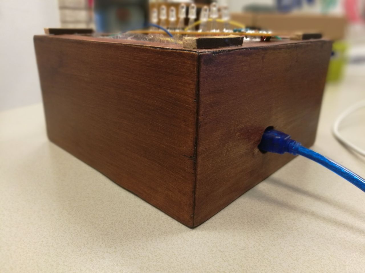
案例:我使用我大學提供的工具制作了這個案例,因此這個工作流程并不適用于所有人。然而,沒有什么特別之處,它需要一側的孔讓USB端口適合穿過,但除此之外它只是一個敞開的頂盒。
尺寸如下:
15 x 15 CM用于透明頂部
和
15 x 8 CM用于木制基地(木材的厚度對我來說是1.8厘米)。
我用臺鋸將MDF板切成我需要的正確尺寸(這是4個面板15 x 8 CM和1 15 x 15 CM接地面板),之后我將角切成45度角。我使用木膠和夾子(讓它至少干燥30分鐘)粘在一起的所有部件,我使用相同的程序用于樹脂玻璃,但使用特殊的鋸片。
其中一個木質邊應該在arduino USB插頭高度的中心有一個孔,以便插入arduino。
我完成了單板的基礎。我把它切成比每邊的表面略大的碎片。
我粘上它,然后將它夾在每一邊30分鐘(更好的是單獨做,所以你確保它不會滑動干燥之后,我將切掉的東西切掉了。
我用Acryl特有的膠水粘在一起稱為Acryfix。
請注意,如果你使用丙烯酸樹脂膠,膠水稍微溶解有機玻璃,因此盡可能精確和快速(它在幾分鐘內干燥,但在幾秒鐘內暴露在空氣中)。
為了完成蓋帽,我用噴砂機擦拭了立方體但你也可以使用細砂紙,只需要花費更多的時間使它看起來均勻。但要注意,如果你使用砂紙需要細粒度,并在結霜程序后將部件粘在一起(所以你不要破壞它意外地施加很大的壓力)
為了確保蓋子不會滑到太多,我在木制立方體的邊緣粘了幾個小木條。
第5步:最終結果應該是這樣的:

第6步:焊接!
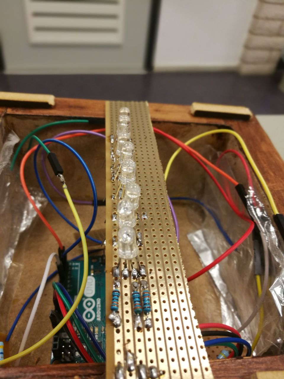

如果您有電路板,您可以使用面包板所具有的相同設置開始將所有部件焊接在一起。
我的電路板有連續的銅條,便于使用。
對于每個傳感器,我切掉一個小方塊,將電阻器和電線焊接到。
發送線(從引腳4到每個傳感器的導線)按順序焊接到一個單獨的方形,1根導線進入引腳4.
我保留了一個長矩形,用于制作一個簡易的LED條(測量它,使其適合帽的內部,但在基座的邊緣)。你可以按順序依次焊接LED(請記住圖像我偶然焊接電路板錯誤一側的LED和電阻,銅條應始終位于底面)。
將各個部件焊接在一起后,將它們裝入外殼中。我沒有將我的單根電線焊接在一起,所以如果需要我可以輕松地將它們更換。
時間讓所有東西都融入基地:
這是最簡單的步驟,arduino需要首先通過USB端口穿過背面的孔這個案子。現在添加傳感器,確保傳感器箔片兩側貼合木材,地面箔片直接貼在上面。當它完全適合時,將RGB LED插入右側引腳(9,10,11)并讓它靠在底座的邊緣。
第7步:完成!
如果您已完成所有這一切,您現在應該有一個帶電容式觸摸顏色混合的工作燈。
-
傳感器
+關注
關注
2565文章
52934瀏覽量
766868 -
Arduino
+關注
關注
190文章
6497瀏覽量
192008
發布評論請先 登錄
中山大學:用于呼吸識別和非接觸式人機交互的均勻快速響應濕度場傳感陣列的可擴展制備

2025上海車展 | 移遠通信重磅發布AR腳踢毫米波雷達,重新定義“無接觸交互”尾門

東軟聯合推出新一代全語言交互式人社服務機器人“南小寧”
中國移動攜手華為打造全國首個5G新通話交互式客服
透明近紅外傳感器推動非接觸式交互應用
請問LMT87屬于接觸式溫度傳感器還是非接觸式溫度傳感器?
米爾-紫光PG2L100H國產FPGA開發板試用】按鍵功能測試報告
Google DeepMind發布Genie 2:打造交互式3D虛擬世界
交互式ups和在線UPS不同點,超過限值

交互式低延遲音頻解碼器

無葉風扇燈的優缺點有哪些
創新科技,智能溫控電吹風 —— Bestow Mascot? 非接觸式測溫模塊


 交互式無接觸燈的制作



評論