") 如何制作Arduino雷達
如何制作Arduino雷達
第1步:材料和程序
此構(gòu)建所需的材料包括:
- 1個伺服
- 1個超聲波傳感器
- 1個蜂鳴器
- 1面包板
- 1 UNO R3 Arduino
- 電線堆
制作此雷達所需的程序:
- Arduino IDE
- 處理3.4
要將上述程序下載到您的計算機上,請點擊以下鏈接:
- https://www.arduino.cc/en/main/software
-https://processing.org/download/
第2步:Arduino代碼
這是arduino代碼,它基本上控制伺服和傳感器的運動和輸入。這是從youtube視頻https://www.youtube.com/watch?v=JvmIutmQd9U復制而來,似乎與我的arduino板和計算機很好地配合。
// Includes the servo library
#include 。
// Defines Trig and Echo pins of the Ultrasonic Sensor
const int trigPin = 10;
const int echoPin = 11;
#define buzzerPin A0 //Defines the pin A0 as an output to buzzerPin
// Variables for the duration and the distance
long duration;
int distance;
Servo myServo; // Creates a servo object for controlling the servo motor
void setup() {
pinMode(trigPin, OUTPUT); // Sets the trigPin as an Output
pinMode(echoPin, INPUT); // Sets the echoPin as an Input
Serial.begin(9600);
myServo.attach(12); // Defines on which pin is the servo motor attached
}
void loop() {
// rotates the servo motor from 15 to 165 degrees
for(int i=15;i《=165;i++){
myServo.write(i);
delay(30);
distance = calculateDistance();// Calls a function for calculating the distance measured by the Ultrasonic sensor for each degree
Serial.print(i); // Sends the current degree into the Serial Port
Serial.print(“,”); // Sends addition character right next to the previous value needed later in the Processing IDE for indexing
Serial.print(distance); // Sends the distance value into the Serial Port
Serial.print(“。”); // Sends addition character right next to the previous value needed later in the Processing IDE for indexing
tone(buzzerPin, 10000 / distance);
}
// Repeats the previous lines from 165 to 15 degrees
for(int i=165;i》15;i--){
myServo.write(i);
delay(30);
distance = calculateDistance();
Serial.print(i);
Serial.print(“,”);
Serial.print(distance);
Serial.print(“。”);
tone(buzzerPin, 10000 / distance); //Produces a different tone according to the distance the object is from the sensor
}
}
// Function for calculating the distance measured by the Ultrasonic sensor
int calculateDistance(){
digitalWrite(trigPin, LOW);
delayMicroseconds(2);
// Sets the trigPin on HIGH state for 10 micro seconds
digitalWrite(trigPin, HIGH);
delayMicroseconds(10);
digitalWrite(trigPin, LOW);
duration = pulseIn(echoPin, HIGH); // Reads the echoPin, returns the sound wave travel time in microseconds
distance= duration*0.034/2;
return distance;
}
步驟3:處理代碼
以下是我用于處理程序從超聲波傳感器獲取信息的代碼,并將其轉(zhuǎn)換為它創(chuàng)建的顯示。這是我從視頻https://www.youtube.com/watch?v=JvmIutmQd9U復制的代碼,該代碼效果非常好,只需要進行一些調(diào)整。
p.p1 {margin: 0.0px 0.0px 0.0px 0.0px; font: 11.0px ‘Helvetica Neue’; color: #000000; -webkit-text-stroke: #000000}
p.p2 {margin: 0.0px 0.0px 0.0px 0.0px; font: 11.0px ‘Helvetica Neue’; color: #000000; -webkit-text-stroke: #000000; min-height: 12.0px}
span.s1 {font-kerning: none}
import processing.serial.*; // imports library for serial communication
import java.awt.event.KeyEvent; // imports library for reading the data from the serial port
import java.io.IOException;
Serial myPort; // defines Object Serial
// defubes variables
String angle=“”;
String distance=“”;
String data=“”;
String noObject;
float pixsDistance;
int iAngle, iDistance;
int index1=0;
int index2=0;
PFont orcFont;
void setup() {
size (1200, 700); // ***CHANGE THIS TO YOUR SCREEN RESOLUTION***
smooth();
myPort = new Serial(this,“/dev/cu.usbmodem143401”, 9600); // starts the serial communication
myPort.bufferUntil(‘。’); // reads the data from the serial port up to the character ‘。’. So actually it reads this: angle,distance.
}
void draw() {
fill(98,245,31);
// simulating motion blur and slow fade of the moving line
noStroke();
fill(0,4);
rect(0, 0, width, height-height*0.065);
fill(98,245,31); // green color
// calls the functions for drawing the radar
drawRadar();
drawLine();
drawObject();
drawText();
}
void serialEvent (Serial myPort) { // starts reading data from the Serial Port
// reads the data from the Serial Port up to the character ‘。’ and puts it into the String variable “data”。
data = myPort.readStringUntil(‘。’);
data = data.substring(0,data.length()-1);
index1 = data.indexOf(“,”); // find the character ‘,’ and puts it into the variable “index1”
angle= data.substring(0, index1); // read the data from position “0” to position of the variable index1 or thats the value of the angle the Arduino Board sent into the Serial Port
distance= data.substring(index1+1, data.length()); // read the data from position “index1” to the end of the data pr thats the value of the distance
// converts the String variables into Integer
iAngle = int(angle);
iDistance = int(distance);
}
void drawRadar() {
pushMatrix();
translate(width/2,height-height*0.074); // moves the starting coordinats to new location
noFill();
strokeWeight(2);
stroke(98,245,31);
// draws the arc lines
arc(0,0,(width-width*0.0625),(width-width*0.0625),PI,TWO_PI);
arc(0,0,(width-width*0.27),(width-width*0.27),PI,TWO_PI);
arc(0,0,(width-width*0.479),(width-width*0.479),PI,TWO_PI);
arc(0,0,(width-width*0.687),(width-width*0.687),PI,TWO_PI);
// draws the angle lines
line(-width/2,0,width/2,0);
line(0,0,(-width/2)*cos(radians(30)),(-width/2)*sin(radians(30)));
line(0,0,(-width/2)*cos(radians(60)),(-width/2)*sin(radians(60)));
line(0,0,(-width/2)*cos(radians(90)),(-width/2)*sin(radians(90)));
line(0,0,(-width/2)*cos(radians(120)),(-width/2)*sin(radians(120)));
line(0,0,(-width/2)*cos(radians(150)),(-width/2)*sin(radians(150)));
line((-width/2)*cos(radians(30)),0,width/2,0);
popMatrix();
}
void drawObject() {
pushMatrix();
translate(width/2,height-height*0.074); // moves the starting coordinats to new location
strokeWeight(9);
stroke(255,10,10); // red color
pixsDistance = iDistance*((height-height*0.1666)*0.025); // covers the distance from the sensor from cm to pixels
// limiting the range to 40 cms
if(iDistance《40){
// draws the object according to the angle and the distance
line(pixsDistance*cos(radians(iAngle)),-pixsDistance*sin(radians(iAngle)),(width-width*0.505)*cos(radians(iAngle)),-(width-width*0.505)*sin(radians(iAngle)));
}
popMatrix();
}
void drawLine() {
pushMatrix();
strokeWeight(9);
stroke(30,250,60);
translate(width/2,height-height*0.074); // moves the starting coordinats to new location
line(0,0,(height-height*0.12)*cos(radians(iAngle)),-(height-height*0.12)*sin(radians(iAngle))); // draws the line according to the angle
popMatrix();
}
void drawText() { // draws the texts on the screen
pushMatrix();
if(iDistance》40) {
noObject = “Out of Range”;
}
else {
noObject = “In Range”;
}
fill(0,0,0);
noStroke();
rect(0, height-height*0.0648, width, height);
fill(98,245,31);
textSize(25);
text(“10cm”,width-width*0.3854,height-height*0.0833);
text(“20cm”,width-width*0.281,height-height*0.0833);
text(“30cm”,width-width*0.177,height-height*0.0833);
text(“40cm”,width-width*0.0729,height-height*0.0833);
textSize(40);
text(“Ryan‘s Radar”, width-width*0.875, height-height*0.0277);
text(“Angle: ” + iAngle +“ °”, width-width*0.48, height-height*0.0277);
text(“Distance: ”, width-width*0.26, height-height*0.0277);
if(iDistance《40) {
text(“ ” + iDistance +“ cm”, width-width*0.225, height-height*0.0277);
}
textSize(25);
fill(98,245,60);
translate((width-width*0.4994)+width/2*cos(radians(30)),(height-height*0.0907)-width/2*sin(radians(30)));
rotate(-radians(-60));
text(“30°”,0,0);
resetMatrix();
translate((width-width*0.503)+width/2*cos(radians(60)),(height-height*0.0888)-width/2*sin(radians(60)));
rotate(-radians(-30));
text(“60°”,0,0);
resetMatrix();
translate((width-width*0.507)+width/2*cos(radians(90)),(height-height*0.0833)-width/2*sin(radians(90)));
rotate(radians(0));
text(“90°”,0,0);
resetMatrix();
translate(width-width*0.513+width/2*cos(radians(120)),(height-height*0.07129)-width/2*sin(radians(120)));
rotate(radians(-30));
text(“120°”,0,0);
resetMatrix();
translate((width-width*0.5104)+width/2*cos(radians(150)),(height-height*0.0574)-width/2*sin(radians(150)));
rotate(radians(-60));
text(“150°”,0,0);
popMatrix();
}
步驟4:超聲波傳感器支架
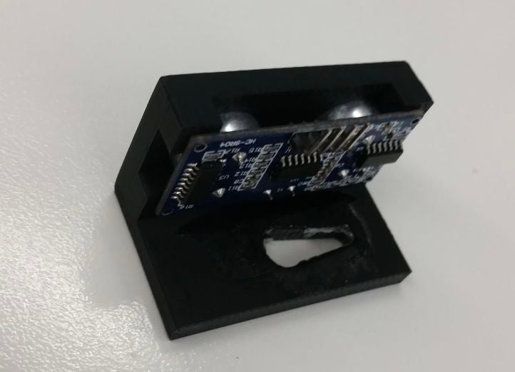
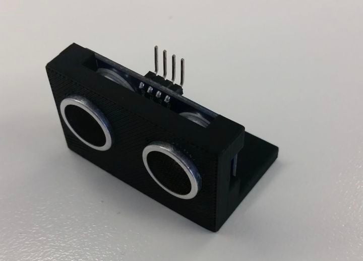
由于我對此項目的啟發(fā)并未包含任何類型的支架來固定超聲波傳感器在適當?shù)奈恢茫覜Q定3D打印這個支架是一個好主意,讓完成的設計看起來更整潔,并使一切更容易組合。保持超聲波傳感器的部分最終相對緊密地安裝在超聲波傳感器周圍,在保持其就位方面做得很好。然而,在下面切出的用于伺服臂進入的孔有點太大,所以我需要添加很多膠水來保持它的位置。但總的來說,它的效果非常好,并且設計看起來很漂亮。
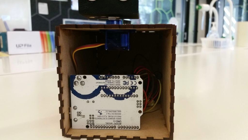
第5步:激光切割盒設計
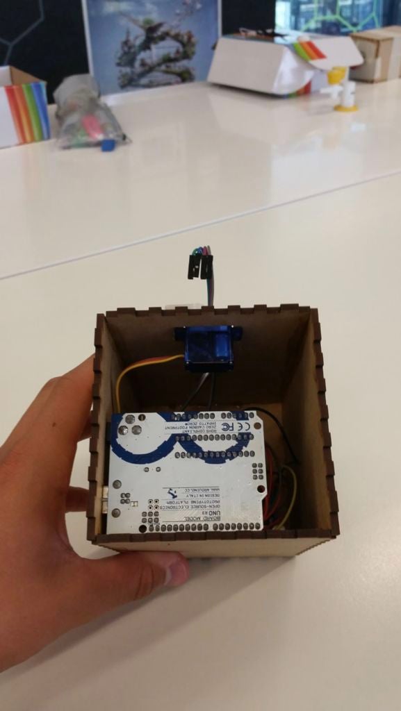
實施此框以使項目具有干凈和專業(yè)的外觀。它在隱藏所有電線和arduino板本身方面做得很好。為了創(chuàng)建實際的盒子設計,我使用網(wǎng)站http://www.makercase.com/來獲得手指邊緣以將盒子的每一側(cè)連接在一起。這是一個非常有用的網(wǎng)站,因為它節(jié)省了我大量的時間,并且非常容易使用。從雷達的成品中可以看出,我在設計的側(cè)面和頂部切出了測量孔,以便允許項目的部分需要在外面。這包括用于伺服的孔,我從下面粘到盒子上,連接到超聲波傳感器,蜂鳴器,以及從計算機到arduino板本身。這是相當大的(盒子里有很多空間),但至少它給你很大的工作空間,沒有任何東西是狹窄的。如果你自己做一個盒子設計,你肯定可以做得更小,一切都會適合。
步驟6:接線構(gòu)造
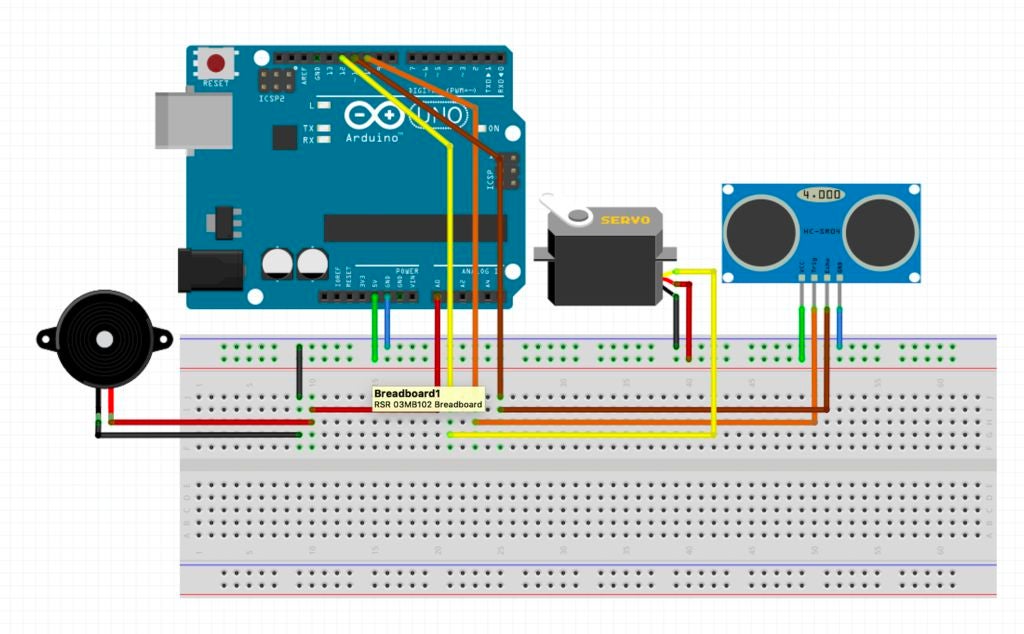
根據(jù)arduino代碼,超聲波傳感器必須連接到引腳10 11.雖然和所有超聲波傳感器一樣,它也必須連接到地和5V引腳。伺服必須連接到引腳12(myServo.attach(12);),它還必須連接到地和5V引腳。至于蜂鳴器,它只接地和模擬輸出引腳A0。一旦你為雷達附加了所有必要的物品,你的電路應該看起來有點像上圖。此外,盡量保持一切整潔!一旦電路在盒子里,電線都非常纏結(jié),有可能一根或兩根電線滑出不到位置并導致雷達發(fā)生故障。它發(fā)生在我身上,我發(fā)現(xiàn)它從那時起就保持整潔,減少了這些事件的發(fā)生。
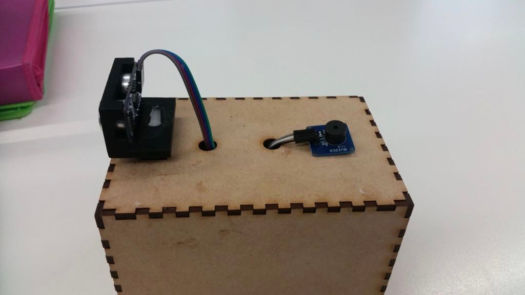
步驟7:組裝
使用強力超級膠水組裝激光切割盒,因此完成后不會有碎片分開雷達。我發(fā)現(xiàn)更容易使用一些書來支撐盒子的一側(cè),這樣我就可以粘上相鄰的一面。在那里拿著它約5分鐘后,我會繼續(xù)到下一側(cè),依此類推。記住不要粘上其中一端,因為你顯然需要放入并取出雷達。一旦盒子上的膠水硬化,您就可以繼續(xù)裝配。首先,我將蜂鳴器粘在外殼的頂部(如上圖所示),然后當它干燥時,我將電線穿過相對的孔并將它們連接到蜂鳴器上。當談到伺服系統(tǒng)時,我將伺服的小翼粘在盒子下面,所以只有伺服的頂部顯示出來。這使得整個產(chǎn)品看起來既美觀又保持其實用性,伺服頭可隨時輕松訪問。然后使用3D打印支架中的超聲波傳感器,使用膠水將支架連接到伺服系統(tǒng),以確保其安全。完成后,您的項目即可進行測試!
步驟8:執(zhí)行
首先將計算機連接到arduino板。接下來,打開兩個程序。加載arduino代碼后,將其上傳到主板。這應該開始伺服和蜂鳴器,因此會產(chǎn)生噪音,伺服也會相應轉(zhuǎn)動。然后,當加載處理代碼時,單擊運行,如果一切順利運行,則應顯示雷達的動畫。如果沒有發(fā)生這種情況,請檢查您使用的端口名稱是否與代碼中的名稱完全相同。例如,如果我使用端口“/dev/cu.usbmodem143401”,請確保處理中的代碼行顯示“myPort = new Serial(this,”/dev/cu.usbmodem143401“,9600);”。這應該解決所有問題,它應該運行順利。啟動和運行的過程都可以在上面的視頻鏈接上看到它正在工作和檢測對象。
-
雷達
+關(guān)注
關(guān)注
50文章
3096瀏覽量
119655 -
Arduino
+關(guān)注
關(guān)注
189文章
6494瀏覽量
190329
發(fā)布評論請先 登錄
免費分享Arduino入門+進階(全套例程+書籍)

《ESP32S3 Arduino開發(fā)指南》第二章 Arduino基礎知識
定華雷達儀表學堂:高頻雷達物位計與低頻雷達物位計的優(yōu)缺點
定華雷達儀表學堂:如何判斷雷達物位計正常工作?
OLED 顯示雷達數(shù)據(jù)


 工商網(wǎng)監(jiān)
評論