") 電池欠壓告警器(英文),Battery Low Voltage Alarm
電池欠壓告警器(英文),Battery Low Voltage Alarm

電池欠壓告警器(英文),Battery Low Voltage Alarm
關(guān)鍵字:電池欠壓告警器
Here is another equally cool low voltage alarm circuit for your glider receiver battery that I've shamelessly stolen from George Steiner's book "A to Z--Radio Control Electronic Journal" (see below). I've modified it to use with small battery packs in R/C gliders. This design has a trigger voltage at about 4.3 volts, and it draws 1mA or less when quiet and about 4mA when buzzing. This can be constructed from parts fromt Radio Shack, though you may need to order a few through them.
The voltage of a receiver system is punctuated by low-voltage spikes every time the servo motors spin up, since the servos draw more than the battery can deliver. With large receiver battery packs, this is not as much of an issue, and it may not be noticeable. However with 270mA and smaller battery packs, particularly with more than two servos, low voltage alarms can chirp constantly, every time a servo moves. The challenge is to design in a little slack or delay, just enough so that you are not annoyed by constant chirping, but not too much so that the chirps can give you a warning before the battery is completely exhausted. Here, this "hysteresis" is adjusted with the capacitor. For large packs (600mA and above), no capacitor is probably needed, although I've been using a 1uF capacitor on my open class ship with 6 servos and a 600mA battery. For 270 mA and two servos, I'd suggest trying a 1uF capacitor. For 150mA or less, a 2.2uF capacitor works well. If you want to know only when the battery has finally reached the trigger voltage, try a 5uF (or 4.7uF) capacitor. The actual type of capacitor is not critical, but tantalum capacitors are physically smaller. If you want to worry about the polarity of the capacitor, the negative side should be directed toward the negative pole of the battery, but at these relatively low voltages compared to the capacitor rating, the polarity probably does not matter.
This circuit is set up for a four cell receiver battery pack at a trigger voltage of about 4.3 volts (about 1.1volts/cell). You can adjust R1 (here a 3.3k resistor) to change the trigger voltage of the circuit. For example, for a 5 cell pack, to change the trigger voltage to 5.5 volts, change R1 to 2.2k. For a three cell pack, to change the trigger voltage to 3.3 volts, change R1 to 6.8 k (or use two 3.3k resistors in parallel by soldering a resistor in each hole and twisting together the top leads). Because of slight variability in tolerances of the componants, you should check this little device with a variable power source and a voltmeter to confirm its trigger point. Alternately, use your digital voltmeter or expanded scale voltmeter to calibrate its chirp pattern by measuring the voltage of the onboard battery pack intermittently as you fly.
Make sure the band on the Zener diode is toward the "+" side (toward R1). Solder a battery connector or servo connector to the board with positive and negative as shown, and plug the connector into an unused slot in your receiver.
Circuit diagram
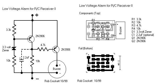
Radio Shack parts: Here again, you can use smaller rated resistors if you can get them--1/8 watt or less is fine. Tantalum capacitors are physically smaller, but any composition will work.
273-074 Miniature Piezo Buzzer, 12v, PC board mount
271-312 1/4 watt 5% carbon film resistors, 500 pieces (Take the plunge!)
276-1604 Package of 15 PNP small signal 2N3906-type transistors. Could use instead 276-2016 $0.59 2N3904 PNP transistors
RSU 11673505 3.3v Zener diode (not on shelf--need to order 1-800-THE-SHACK)
272-1434 1uf tantalum capacitor (see above for choice of capacitor)
RSU 11295888 2.2uF tantalum capacitor (not on shelf--need to order)
272-1024 4.7uF radial-lead electrolytic capacitor
Digikey (1-800-344-4539) part numbers: Digikey does sell the peizo buzzers, but they are much more expensive than those at Radio Shack and are larger as well.
2N3906-ND PNP general purpose amp/switch transistor
1N5226BMSCT-ND 3.3v Zener diode 500mA
3.3KEBK-ND 1/8 watt resistors
4.7KEBK-ND 1/8 watt resistors
10KEBK-ND 1/8 watt resistors
P2105-ND 1.0uF Tantalum capacitor 16volt
P2022-ND 2.2uF Tantalum capacitor 10volt
P2024-ND 4.7uF Tantalum capacitor 10 volt
FP012C-5-ND 3M clear 0.5" heat shrink tubing, 5 feet
George Steiner's book, crammed with cool R/C radio info, can be had for $19.95 postage paid from the following:
GSP AZ Journal
2238 Rogue River Drive
Sacramento CA 95826
phone: 916-362-1962
Author: Rob Crockett 10/99 GSP AZ Journal
2238 Rogue River Drive
Sacramento CA 95826
phone: 916-362-1962
聲明:本文內(nèi)容及配圖由入駐作者撰寫或者入駐合作網(wǎng)站授權(quán)轉(zhuǎn)載。文章觀點僅代表作者本人,不代表電子發(fā)燒友網(wǎng)立場。文章及其配圖僅供工程師學習之用,如有內(nèi)容侵權(quán)或者其他違規(guī)問題,請聯(lián)系本站處理。
舉報投訴
發(fā)布評論請先 登錄
相關(guān)推薦
熱點推薦
dac3171 config5的alarm_dataclk_ gone有告警是什么原因?
使用的是DAC 31717bit模式。FPGA有數(shù)據(jù)輸出,也有隨路時鐘216M。但3171的config5 的alarm_dataclk_ gone有告警。用示波器測試有時鐘216M輸入到DAC里面,DAC無輸出,請問還需要配置其它寄存
發(fā)表于 12-20 07:02
電動車控制器欠壓保護怎樣調(diào)整
電動車控制器的欠壓保護功能是為了保護電池和延長電池壽命而設(shè)計的。當電池電壓下降到某一設(shè)定值時,控
欠壓保護電路
欠壓保護
隨意用畫板畫了一個,用最少的元件,大家看行不行,用在小電流場景的,估計5ma,實際是我用壞的充電寶弄了個小夜燈,白天不亮,晚上一直亮,當然也可以換個紅外開關(guān)的,放在RL位置。
當電源電壓小于3V時,TL431關(guān)斷,使8050截止,RL不再工作。
不知道這個電路行
發(fā)表于 10-10 21:53
使用TPS3700作為負供電軌過壓和欠壓檢測器
電子發(fā)燒友網(wǎng)站提供《使用TPS3700作為負供電軌過壓和欠壓檢測器.pdf》資料免費下載
發(fā)表于 10-09 10:11
?0次下載

欠壓封鎖電路有什么作用
電子設(shè)備和系統(tǒng)中,如電源管理系統(tǒng)、電池管理系統(tǒng)、電機控制系統(tǒng)等。 1. 欠壓封鎖電路的基本原理 欠壓封鎖電路的核心是檢測電源電壓,并在電壓低
欠壓故障是什么原因
欠壓故障是電氣系統(tǒng)中常見的問題,它指的是電壓低于設(shè)備或系統(tǒng)正常運行所需的最小電壓。 欠壓故障的原因 供電線路問題 : 線路老化或損壞,導致電阻增加,電壓下降。 線路連接不良,如松動或腐
欠壓脫扣器怎么判斷好壞
欠壓脫扣器是一種用于保護電氣設(shè)備在電壓過低時自動斷開電源的裝置。它的主要作用是在電網(wǎng)電壓下降到設(shè)定的閾值以下時,自動切斷電路,以保護設(shè)備不受損壞。判斷欠
欠壓脫扣器合不上閘的原因
欠壓脫扣器合不上閘的原因可能涉及多個方面,主要包括電氣故障和機械故障兩大類。以下是對這些原因的具體分析: 一、電氣故障 欠壓脫扣
欠壓檢測電路工作原理是什么
的基本概念 欠壓檢測電路的核心功能是監(jiān)測電源電壓,并在電壓低于預設(shè)閾值時發(fā)出警告或采取保護措施。這種電路通常包含電壓比較器、邏輯電路、觸發(fā)器等組件。 2. 工作原理 2.1 電壓比較
寬VIN過壓和欠壓監(jiān)控器的常見應用
電子發(fā)燒友網(wǎng)站提供《寬VIN過壓和欠壓監(jiān)控器的常見應用.pdf》資料免費下載
發(fā)表于 09-02 10:13
?0次下載
饋電開關(guān)欠壓保護動作怎么解決
饋電開關(guān)欠壓保護動作是指當電網(wǎng)電壓低于設(shè)定值時,饋電開關(guān)會自動斷開,以保護用電設(shè)備不受電壓過低的影響。解決饋電開關(guān)欠壓保護動作的問題,需要從多個方面進行分析和處理。 一、饋電開關(guān)
400饋電開關(guān)欠壓怎么調(diào)
1. 了解400V饋電開關(guān) 400V饋電開關(guān)是一種用于電力系統(tǒng)的設(shè)備,通常用于工業(yè)和商業(yè)環(huán)境中。它們的主要功能是控制和保護電路,防止過載和短路。欠壓保護是饋電開關(guān)的一個重要功能,用于在電壓下降到設(shè)定


 工商網(wǎng)監(jiān)
評論