") 怎樣用聲音控制RGBLED的顏色
怎樣用聲音控制RGBLED的顏色
連接RGB LED的最長(zhǎng)腳到Arduino。通過(guò)220歐姆電阻將其他支路連接到Arduino的引腳9,10和11,如下面的電路圖所示。

如何運(yùn)行程序
首先,粘貼在Arduino IDE中本文末尾為Arduino提供的代碼并上傳代碼。
然后,您需要從Wekinator的示例頁(yè)面下載草圖。
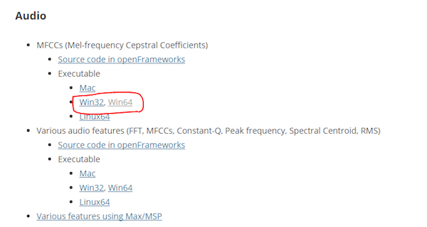
下載MFCC的可執(zhí)行文件(mel頻率倒頻譜系數(shù))。我有一個(gè)64位操作系統(tǒng),所以我從那里下載了“win64”。
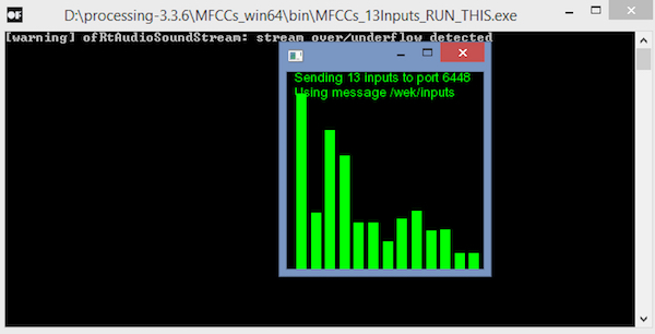
下載后,解壓縮并運(yùn)行“.exe”文件。它將如下所示。現(xiàn)在您需要一個(gè)麥克風(fēng)來(lái)為Wekinator提供輸入。如果您已連接外接麥克風(fēng),請(qǐng)確保在計(jì)算機(jī)的聲音設(shè)置中選擇它。
您將需要另一個(gè)草圖(“輸出草圖”) )從Wekinator獲得輸出。該草圖在本文末尾給出。將其粘貼到新的處理窗口并運(yùn)行草圖。
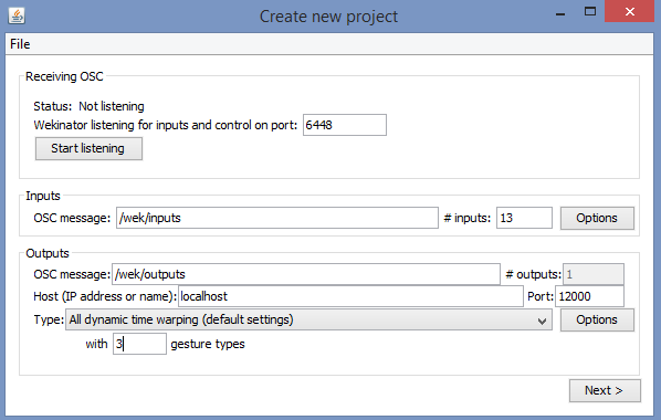
現(xiàn)在打開(kāi)Wekinator并進(jìn)行如下圖所示的設(shè)置。將輸入設(shè)置為13,將輸出設(shè)置為1.將類(lèi)型設(shè)置為“所有動(dòng)態(tài)時(shí)間扭曲”,使用3種手勢(shì)類(lèi)型,然后單擊“下一步”。
現(xiàn)在按住output_1前面的“+”按鈕并說(shuō)“紅色”。
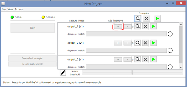
然后按住output_2前面的“+”按鈕并說(shuō)“綠色”。
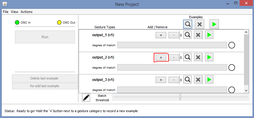
然后按住output_3前面的“+”按鈕并說(shuō)“藍(lán)色”。

之后,單擊“Train”,然后單擊“Run”。現(xiàn)在,RGB LED的顏色將根據(jù)您說(shuō)的顏色名稱(chēng)而改變。
Arduino代碼
#include //Including the library that will help us in receiving and sending the values from processing
ValueReceiver《1》 receiver; /*Creating the receiver that will receive 1 value.
Put the number of values to synchronize in the brackets */
/* The below variable will be synchronized in the processing
and they should be same on both sides. */
int output;
// Initializing the pins for led‘s
int red_light_pin= 11;
int green_light_pin = 10;
int blue_light_pin = 9;
void setup()
{
/* Starting the serial communication because we are communicating with the
Processing through serial. The baudrate should be same as on the processing side. */
Serial.begin(19200);
pinMode(red_light_pin, OUTPUT);
pinMode(green_light_pin, OUTPUT);
pinMode(blue_light_pin, OUTPUT);
// Synchronizing the variable with the processing. The variable must be int type.
receiver.observe(output);
}
void loop()
{
// Receiving the output from the processing.
receiver.sync();
// Matching the received output to light up the RGB LED
if (output == 1)
{
RGB_color(255, 0, 0); // Red
}
else if (output == 2)
{
RGB_color(0, 255, 0); // Green
}
else if (output ==3)
{
RGB_color(0, 0, 255); // Blue
}
}
void RGB_color(int red_light_value, int green_light_value, int blue_light_value)
{
analogWrite(red_light_pin, red_light_value);
analogWrite(green_light_pin, green_light_value);
analogWrite(blue_light_pin, blue_light_value);
}
處理代碼(輸出草圖)
import vsync.*; // Importing the library that will help us in sending and receiving the values from the Arduino
import processing.serial.*; // Importing the serial library
// Below libraries will connect and send, receive the values from wekinator
import oscP5.*;
import netP5.*;
// Creating the instances
OscP5 oscP5;
NetAddress dest;
ValueSender sender;
// This variable will be syncronized with the Arduino and it should be same on the Arduino side.
public int output;
void setup()
{
// Starting the serial communication, the baudrate and the com port should be same as on the Arduino side.
Serial serial = new Serial(this, “COM10”, 19200);
sender = new ValueSender(this, serial);
// Synchronizing the variable as on the Arduino side.
sender.observe(“output”);
// Starting the communication with wekinator. listen on port 12000, return messages on port 6448
oscP5 = new OscP5(this, 12000);
dest = new NetAddress(“127.0.0.1”, 6448);
}
//This is called automatically when OSC message is received
void oscEvent(OscMessage theOscMessage) {
if (theOscMessage.checkAddrPattern(“/output_1”)==true)
{
output = 1;
}
else if (theOscMessage.checkAddrPattern(“/output_2”)==true)
{
output = 2;
}
else if (theOscMessage.checkAddrPattern(“/output_3”) == true)
{
output = 3;
}
else
{
}
}
void draw()
{
// Nothing to be drawn for this example
}
-
led
+關(guān)注
關(guān)注
242文章
23741瀏覽量
671360 -
Arduino
+關(guān)注
關(guān)注
189文章
6493瀏覽量
190203
發(fā)布評(píng)論請(qǐng)先 登錄
PCBA板的顏色密碼:選美大賽還是實(shí)用主義?
DLPC150采用I2C控制時(shí),如何控制LED開(kāi)關(guān)?如何控制顯示的顏色?
如何選擇PCB顏色
將AIC33的DIN和DOUT腳用短路的方式實(shí)現(xiàn)自環(huán)時(shí),說(shuō)話的聲音稍微大點(diǎn)的時(shí)候,會(huì)在聲音上疊加一個(gè)“噼啪”聲,為什么?
用TPA3001做音頻信號(hào)的功放,輸出的聲音很沙啞是怎么回事?
請(qǐng)問(wèn)TAS5706如何用硬件控制I2C?
Tas2555聲音通訊已實(shí)現(xiàn),音量控制用這個(gè)寄存器Speaker Control Register實(shí)現(xiàn)嗎?
多個(gè)TLV320AIC3254用一路I2C總線對(duì)其配置可行嗎?
如何用5509A產(chǎn)生一個(gè)白噪聲,經(jīng)AIC23播放出來(lái)然后再用AIC23采集這個(gè)聲音?
探秘PCB板顏色:從外觀到內(nèi)涵的多重解讀
怎樣用自己的電腦遠(yuǎn)程公司的電腦

OPA735加OPA333,怎樣用TINA TI去仿真?
怎樣用萬(wàn)用表測(cè)穩(wěn)壓管穩(wěn)壓值
EPSON公司發(fā)布帶有專(zhuān)用于2聲道聲音的聲音硬件的32位微控制器


 工商網(wǎng)監(jiān)
評(píng)論