本帖最后由 donatello1996 于 2025-6-14 22:51 編輯
原定項(xiàng)目?jī)?nèi)容:
1.基于板載段碼LCD顯示屏制作一個(gè)簡(jiǎn)易\"電壓檢測(cè)器\"(SLCDC和ADC);(因占用IO沖突的原因放棄,并且其他試用者已經(jīng)做了詳細(xì)評(píng)測(cè))
2.低功耗功能(評(píng)估MCU的節(jié)能性能),使用INA219模塊檢測(cè)開(kāi)發(fā)板運(yùn)行時(shí)電流大小,就可以得出開(kāi)發(fā)板運(yùn)行功率;(INA219模塊通信失敗,放棄)
3.使用開(kāi)發(fā)板的SPI接口接入NRF24L01模塊,進(jìn)行2.4G無(wú)線通信;(成功)
4..使用開(kāi)發(fā)板的I2C接口接入BMP280模塊,檢測(cè)大氣壓數(shù)值;(成功)
新增已完成項(xiàng)目?jī)?nèi)容:
5.使用QSPI總線讀寫(xiě)QSPI FLASH;
6.使用模擬I2C總線
首先,在開(kāi)始任何開(kāi)發(fā)之前,需要下載最新版本的RASC安裝包,我這里下載的是FSP5.9的安裝包,使用新版本RASC安裝包以便支持RA4L1新系列的開(kāi)發(fā):
硬件框圖:
流程圖:
串口打印直接使用開(kāi)發(fā)板USB Type-C接口的USB轉(zhuǎn)TTL,也就是SCI9(P109和P110),使用KEIL自帶的microLIB選項(xiàng),程序引用stdio.h,覆寫(xiě)fputc函數(shù)原型即可直接支持printf串口打印(RTT kprintf后面有機(jī)會(huì)再進(jìn)行嘗試,串口用習(xí)慣了):
#include
#include \"hal_data.h\"
int fputc(int ch, FILE *f)
{
(void)f;
while(!g_uart9_ctrl.p_reg->SSR_b.TEND);
g_uart9_ctrl.p_reg->TDR = (uint8_t)ch;
return ch;
}
顯示用的SPITFTLCD4.3寸液晶屏是一款帶CPLD主控和SDRAM的液晶屏,通過(guò)SPI接口進(jìn)行指令傳輸,刷屏和顯示字符的能力很強(qiáng),唯一不足的是刷圖效率低,可以通過(guò)GPIO模擬SPI方式直接驅(qū)動(dòng),占用三個(gè)引腳,分別為P500 P502 P504:
#define SPILCD43_FAKE_SPI_CS_LOWR_IOPORT_PinWrite(&g_ioport_ctrl, BSP_IO_PORT_05_PIN_00 , BSP_IO_LEVEL_LOW)
#define SPILCD43_FAKE_SPI_CS_HIGHR_IOPORT_PinWrite(&g_ioport_ctrl, BSP_IO_PORT_05_PIN_00 , BSP_IO_LEVEL_HIGH)
#define SPILCD43_FAKE_SPI_CLK_LOWR_IOPORT_PinWrite(&g_ioport_ctrl, BSP_IO_PORT_05_PIN_02 , BSP_IO_LEVEL_LOW)
#define SPILCD43_FAKE_SPI_CLK_HIGHR_IOPORT_PinWrite(&g_ioport_ctrl, BSP_IO_PORT_05_PIN_02 , BSP_IO_LEVEL_HIGH)
#define SPILCD43_FAKE_SPI_DI_LOWR_IOPORT_PinWrite(&g_ioport_ctrl, BSP_IO_PORT_05_PIN_04 , BSP_IO_LEVEL_LOW)
#define SPILCD43_FAKE_SPI_DI_HIGHR_IOPORT_PinWrite(&g_ioport_ctrl, BSP_IO_PORT_05_PIN_04 , BSP_IO_LEVEL_HIGH)
void Fake_SPI_WriteByte(uint8_t data)
{
uint8_t i = 0 , temp = 0;
for(i = 0 ; i < 8 ; i++)
{
temp = ((data&0x80)==0x80) ? 1:0;
data = data << 1;
SPILCD43_FAKE_SPI_CLK_LOW;
if(temp)
SPILCD43_FAKE_SPI_DI_HIGH;
else
SPILCD43_FAKE_SPI_DI_LOW;
R_BSP_SoftwareDelay(2 , BSP_DELAY_UNITS_MICROSECONDS);
SPILCD43_FAKE_SPI_CLK_HIGH;
R_BSP_SoftwareDelay(2 , BSP_DELAY_UNITS_MICROSECONDS);
}
SPILCD43_FAKE_SPI_CLK_HIGH;
}
void LCD_send_command(uint8_t out_cmd)
{
SPILCD43_FAKE_SPI_CS_LOW;
Fake_SPI_WriteByte(out_cmd);
SPILCD43_FAKE_SPI_CS_HIGH;
}
void LCD_send_data(uint32_t out_data)
{
SPILCD43_FAKE_SPI_CS_LOW;
Fake_SPI_WriteByte((out_data >> 8) & 0xff);
Fake_SPI_WriteByte(out_data & 0xff);
SPILCD43_FAKE_SPI_CS_HIGH;
}
void LCD_write_com(uint32_t addr , uint32_t num)
{
LCD_send_command(addr & 0xff);
LCD_send_data(num);
}
void LCD_Set_Windows(unsigned int x0, unsigned int y0,unsigned int x1, unsigned int y1)
{
LCD_write_com(CMD_Xaddr_Start ,x0);
LCD_write_com(CMD_Xaddr_End ,x1);
LCD_write_com(CMD_Yaddr_Start ,y0);
LCD_write_com(CMD_Yaddr_End ,y1);
LCD_write_com(CMD_Xaddr, x0);
LCD_write_com(CMD_Yaddr, y0);
}
void LCD_SET_FRONT(uint16_t color)
{
LCD_write_com(CMD_FRONT , color);
LCD_send_command(CMD_Data);
}
void LCD_SET_BACK(uint16_t color)
{
LCD_write_com(CMD_BACK,color);
LCD_send_command(CMD_Data);
}
void LCD_SET_Backlight(unsigned char BLK_num)
{
LCD_PWM = BLK_num;
LCD_write_com(CMD_Ctrl , LCD_PWM);
}
void LCD_Set_ramaddr(unsigned int x,unsigned int y)
{
LCD_write_com(CMD_Yaddr,y);
LCD_write_com(CMD_Xaddr,x);
}
void LCD_RectangleFill(unsigned int x0 , unsigned int y0 ,unsigned int x1 , unsigned int y1 , uint16_t color)
{
LCD_Set_Windows(x0,y0,x1,y1);
LCD_SET_FRONT(color);
LCD_write_com(CMD_Ctrl , CMD_Ctrl_Fill);
//while(TFT_BUSY==0);
R_BSP_SoftwareDelay(20 , BSP_DELAY_UNITS_MILLISECONDS);
LCD_Set_Windows(0 , 0 , (LCD_XSIZE-1) , (LCD_YSIZE-1));
}
void DispClear_LCD(uint16_t color)
{
LCD_RectangleFill(0 , 0 , (LCD_XSIZE-1) , (LCD_YSIZE-1) , color);
}
void LCD_DrawString(unsigned int x, unsigned int y, unsigned char *pStr, unsigned int LineColor,unsigned int FillColor, unsigned char CMD_CHAR_MOD)
{
LCD_SET_FRONT(LineColor);
LCD_SET_BACK(FillColor);
LCD_Set_ramaddr(x,y);
while(*pStr>0)
{
if (*pStr > 0x80)
{
LCD_write_com(CMD_CHAR_MOD , ((*pStr)<<8)+(*(pStr+1)));
pStr += 2;
}
else
{
LCD_write_com(CMD_CHAR_MOD , *pStr);
pStr += 1;
}
}
R_BSP_SoftwareDelay(20 , BSP_DELAY_UNITS_MILLISECONDS);
}
然后是NRF24L01模塊,設(shè)置為接收模式,占用硬件SPI0接口,直接接到Arduino的那組SPI接口(P210 P211 P209)上即可,并需要額外占用SPI0接口下方的P204 P600 P602三個(gè)引腳分別用作片選 CE IRQ功能:
#define NRF24L01_CS_HIGHR_IOPORT_PinWrite(&g_ioport_ctrl, BSP_IO_PORT_02_PIN_04 , BSP_IO_LEVEL_HIGH)
#define NRF24L01_CS_LOWR_IOPORT_PinWrite(&g_ioport_ctrl, BSP_IO_PORT_02_PIN_04 , BSP_IO_LEVEL_LOW)
//P204 D10
#define NRF24L01_CE_HIGHR_IOPORT_PinWrite(&g_ioport_ctrl, BSP_IO_PORT_06_PIN_00 , BSP_IO_LEVEL_HIGH)
#define NRF24L01_CE_LOWR_IOPORT_PinWrite(&g_ioport_ctrl, BSP_IO_PORT_06_PIN_00 , BSP_IO_LEVEL_LOW)
//P600 D9
//#define NRF24L01_IRQ_READ
//P602 D8
#define NRF_READ_REG 0x00
#define NRF_WRITE_REG0x20
#define RD_RX_PLOAD0x61
#define WR_TX_PLOAD0xA0
#define FLUSH_TX0xE1
#define FLUSH_RX0xE2
#define REUSE_TX_PL0xE3
#define NOP 0xFF
#define CONFIG 0x00
#define EN_AA0x01
#define EN_RXADDR 0x02
#define SETUP_AW0x03
#define SETUP_RETR0x04
#define RF_CH0x05
#define RF_SETUP 0x06
#define STATUS 0x07
#define MAX_TX0x10
#define TX_OK0x20
#define RX_OK0x40
#define OBSERVE_TX0x08
#define CD0x09
#define RX_ADDR_P00x0A
#define RX_ADDR_P10x0B
#define RX_ADDR_P20x0C
#define RX_ADDR_P30x0D
#define RX_ADDR_P40x0E
#define RX_ADDR_P50x0F
#define TX_ADDR0x10
#define RX_PW_P00x11
#define RX_PW_P10x12
#define RX_PW_P20x13
#define RX_PW_P30x14
#define RX_PW_P40x15
#define RX_PW_P50x16
#define NRF_FIFO_STATUS 0x17
#define TX_ADR_WIDTH 5
#define RX_ADR_WIDTH 5
#define TX_PLOAD_WIDTH32
#define RX_PLOAD_WIDTH32
const uint8_t TX_ADDRESS[TX_ADR_WIDTH]={0x34,0x43,0x10,0x10,0x01};
const uint8_t RX_ADDRESS[RX_ADR_WIDTH]={0x34,0x43,0x10,0x10,0x01};
uint8_t SPI0_P209_210_P211_Read_Write_Byte(uint8_t txdata)
{
uint8_t rxdata;
R_SPI_WriteRead(&g_spi0_ctrl , &txdata , &rxdata , 1 , 4);
return rxdata;
}
uint8_t NRF24L01_Write_Buf(uint8_t reg , uint8_t *pBuf , uint8_t len)
{
uint8_t status , u8_ctr;
NRF24L01_CS_LOW;
status = SPI0_P209_210_P211_Read_Write_Byte(reg);
for(u8_ctr = 0 ; u8_ctr < len ; u8_ctr ++)
SPI0_P209_210_P211_Read_Write_Byte(*pBuf++);
NRF24L01_CS_HIGH;
return status;
}
uint8_t NRF24L01_Read_Buf(uint8_t reg , uint8_t *pBuf , uint8_t len)
{
uint8_t status , u8_ctr;
NRF24L01_CS_LOW;
status = SPI0_P209_210_P211_Read_Write_Byte(reg);
for(u8_ctr = 0 ; u8_ctr < len ; u8_ctr ++)
pBuf[u8_ctr] = SPI0_P209_210_P211_Read_Write_Byte(0xff);
NRF24L01_CS_HIGH;
return status;
}
uint8_t NRF24L01_Write_Reg(uint8_t reg , uint8_t value)
{
uint8_t status;
NRF24L01_CS_LOW;
status = SPI0_P209_210_P211_Read_Write_Byte(reg);
SPI0_P209_210_P211_Read_Write_Byte(value);
NRF24L01_CS_HIGH;
return(status);
}
uint8_t NRF24L01_Read_Reg(uint8_t reg)
{
uint8_t reg_val;
NRF24L01_CS_LOW;
SPI0_P209_210_P211_Read_Write_Byte(reg);
reg_val = SPI0_P209_210_P211_Read_Write_Byte(0XFF);
NRF24L01_CS_HIGH;
return(reg_val);
}
uint8_t NRF24L01_Check(void)
{
uint8_t buf[5]={0xa5 , 0xa5 , 0xa5 , 0xa5 , 0xa5};
uint8_t i;
NRF24L01_Write_Buf(NRF_WRITE_REG + TX_ADDR , buf , 5);
NRF24L01_Read_Buf(TX_ADDR , buf , 5);
for(i=0;i<5;i++)
if(buf!=0XA5)
break;
if(i!=5)
return 1;
return 0;
}
uint8_t NRF24L01_RxPacket(uint8_t *rxbuf)
{
uint8_t sta;
sta = NRF24L01_Read_Reg(STATUS);
NRF24L01_Write_Reg(NRF_WRITE_REG + STATUS , sta);
if(sta & RX_OK)
{
printf(\"sta = 0x%x RX_OK.\\n\" , sta);
NRF24L01_Read_Buf(RD_RX_PLOAD , rxbuf , RX_PLOAD_WIDTH);
NRF24L01_Write_Reg(FLUSH_RX , 0xff);
return 0;
}
return 1;
}
void NRF24L01_RX_Mode(void)
{
NRF24L01_CE_LOW;
NRF24L01_Write_Buf(NRF_WRITE_REG+RX_ADDR_P0,(uint8_t*)RX_ADDRESS,RX_ADR_WIDTH);
NRF24L01_Write_Reg(NRF_WRITE_REG+EN_AA,0x01);
NRF24L01_Write_Reg(NRF_WRITE_REG+EN_RXADDR,0x01);
NRF24L01_Write_Reg(NRF_WRITE_REG+RF_CH,40);
NRF24L01_Write_Reg(NRF_WRITE_REG+RX_PW_P0,RX_PLOAD_WIDTH);
NRF24L01_Write_Reg(NRF_WRITE_REG+RF_SETUP,0x0f);
NRF24L01_Write_Reg(NRF_WRITE_REG+CONFIG, 0x0f);
NRF24L01_CE_HIGH;
}
BMP280模塊則是使用P402 P403 GPIO模擬I2C進(jìn)行通信,注意P403需設(shè)置為開(kāi)漏輸出模式:
#define I2C_SCL_P402_HIGHR_IOPORT_PinWrite(&g_ioport_ctrl, BSP_IO_PORT_04_PIN_02 , BSP_IO_LEVEL_HIGH)
#define I2C_SCL_P402_LOWR_IOPORT_PinWrite(&g_ioport_ctrl, BSP_IO_PORT_04_PIN_02 , BSP_IO_LEVEL_LOW)
#define I2C_SDA_P403_HIGHR_IOPORT_PinWrite(&g_ioport_ctrl, BSP_IO_PORT_04_PIN_03 , BSP_IO_LEVEL_HIGH)
#define I2C_SDA_P403_LOWR_IOPORT_PinWrite(&g_ioport_ctrl, BSP_IO_PORT_04_PIN_03 , BSP_IO_LEVEL_LOW)
void I2C_IDLE_P402_P403()
{
I2C_SDA_P403_OUT();
I2C_SDA_P403_HIGH;
I2C_SCL_P402_HIGH;
R_BSP_SoftwareDelay(4 , BSP_DELAY_UNITS_MICROSECONDS);
}
void I2C_Start_P402_P403(void)
{
I2C_SDA_P403_OUT();
I2C_SDA_P403_HIGH;
I2C_SCL_P402_HIGH;
R_BSP_SoftwareDelay(4 , BSP_DELAY_UNITS_MICROSECONDS);
I2C_SDA_P403_LOW;
R_BSP_SoftwareDelay(4 , BSP_DELAY_UNITS_MICROSECONDS);
I2C_SCL_P402_LOW;
R_BSP_SoftwareDelay(4 , BSP_DELAY_UNITS_MICROSECONDS);
}
void I2C_Stop_P402_P403(void)
{
I2C_SDA_P403_OUT();
I2C_SDA_P403_LOW;
I2C_SCL_P402_HIGH;
R_BSP_SoftwareDelay(4 , BSP_DELAY_UNITS_MICROSECONDS);
I2C_SDA_P403_HIGH;
}
uint8_t I2C_Wait_Ack_P402_P403(void)
{
uint8_t rvalue;
I2C_SDA_P403_OUT();
I2C_SDA_P403_HIGH;
R_BSP_SoftwareDelay(4 , BSP_DELAY_UNITS_MICROSECONDS);
I2C_SCL_P402_HIGH;
R_BSP_SoftwareDelay(4 , BSP_DELAY_UNITS_MICROSECONDS);
I2C_SDA_P403_IN();
if(I2C_SDA_P403_READ())
{
rvalue = 1;
}
else
{
rvalue = 0;
}
I2C_SCL_P402_LOW;
R_BSP_SoftwareDelay(4 , BSP_DELAY_UNITS_MICROSECONDS);
return rvalue;
}
void I2C_Ack_P402_P403(void)
{
I2C_SDA_P403_OUT();
I2C_SDA_P403_LOW;
R_BSP_SoftwareDelay(4 , BSP_DELAY_UNITS_MICROSECONDS);
I2C_SCL_P402_HIGH;
R_BSP_SoftwareDelay(4 , BSP_DELAY_UNITS_MICROSECONDS);
I2C_SCL_P402_LOW;
R_BSP_SoftwareDelay(4 , BSP_DELAY_UNITS_MICROSECONDS);
I2C_SDA_P403_HIGH;
}
void I2C_NAck_P402_P403(void)
{
I2C_SDA_P403_OUT();
I2C_SDA_P403_HIGH;
R_BSP_SoftwareDelay(4 , BSP_DELAY_UNITS_MICROSECONDS);
I2C_SCL_P402_HIGH;
R_BSP_SoftwareDelay(4 , BSP_DELAY_UNITS_MICROSECONDS);
I2C_SCL_P402_LOW;
R_BSP_SoftwareDelay(4 , BSP_DELAY_UNITS_MICROSECONDS);
}
void I2C_Send_Byte_P402_P403(uint8_t txd)
{
uint8_t i;
I2C_SDA_P403_OUT();
I2C_SCL_P402_LOW;
for(i = 0 ; i < 8 ; i ++)
{
if((txd&0x80)>>7)
I2C_SDA_P403_HIGH;
else
I2C_SDA_P403_LOW;
txd <<= 1;
R_BSP_SoftwareDelay(20 , BSP_DELAY_UNITS_MICROSECONDS);
I2C_SCL_P402_HIGH;
R_BSP_SoftwareDelay(20 , BSP_DELAY_UNITS_MICROSECONDS);
I2C_SCL_P402_LOW;
R_BSP_SoftwareDelay(20 , BSP_DELAY_UNITS_MICROSECONDS);
}
R_BSP_SoftwareDelay(20 , BSP_DELAY_UNITS_MICROSECONDS);
}
uint16_t I2C_Read_Byte_P402_P403(uint8_t ack)
{
uint8_t i;
uint16_t dat = 0;
I2C_SDA_P403_IN();
for(i = 0 ; i < 8 ; i++)
{
I2C_SCL_P402_LOW;
R_BSP_SoftwareDelay(20 , BSP_DELAY_UNITS_MICROSECONDS);
I2C_SCL_P402_HIGH;
dat <<= 1;
if(I2C_SDA_P403_READ())
dat++;
R_BSP_SoftwareDelay(20 , BSP_DELAY_UNITS_MICROSECONDS);
}
if (!ack)
I2C_NAck_P402_P403();
else
I2C_Ack_P402_P403();
return dat;
}
uint8_t I2C_Read_Addr_P402_P403(uint8_t dev_addr , uint8_t reg)
{
uint8_t res;
I2C_Start_P402_P403();
I2C_Send_Byte_P402_P403((dev_addr << 1) | 0);
I2C_Wait_Ack_P402_P403();
I2C_Send_Byte_P402_P403(reg);
I2C_Wait_Ack_P402_P403();
I2C_Start_P402_P403();
I2C_Send_Byte_P402_P403((dev_addr << 1) | 1);
I2C_Wait_Ack_P402_P403();
res = I2C_Read_Byte_P402_P403(0);
I2C_Stop_P402_P403();
return res;
}
void I2C_Read_Datas_P100_P101(uint8_t dev_addr , uint8_t reg , uint8_t data_len , uint8_t data[])
{
while(data_len)
{
*data = I2C_Read_Addr_P402_P403(dev_addr , reg++);
data ++;
data_len --;
}
}
void I2C_Write_Reg_Data_P402_P403(uint8_t dev_addr , uint8_t reg , uint8_t data)
{
I2C_Start_P402_P403();
I2C_Send_Byte_P402_P403((dev_addr << 1) | 0);
I2C_Wait_Ack_P402_P403();
I2C_Send_Byte_P402_P403(reg);
I2C_Wait_Ack_P402_P403();
I2C_Send_Byte_P402_P403(data);
I2C_Wait_Ack_P402_P403();
I2C_Stop_P402_P403();
}
void I2C_Write_Reg_Datas_P402_P403(uint8_t dev_addr , uint8_t reg , uint8_t data_len , uint8_t data[])
{
int i;
I2C_Start_P402_P403();
I2C_Send_Byte_P402_P403((dev_addr << 1) | 0);
I2C_Wait_Ack_P402_P403();
I2C_Send_Byte_P402_P403(reg);
I2C_Wait_Ack_P402_P403();
for(i = 0 ; i < data_len ; i++)
{
I2C_Send_Byte_P402_P403(data);
I2C_Wait_Ack_P402_P403();
}
I2C_Stop_P402_P403();
R_BSP_SoftwareDelay(10 , BSP_DELAY_UNITS_MILLISECONDS);
}
#define ATH20_SLAVE_ADDRESS0x38
#define BMP280_PRESSURE_OSR (BMP280_OVERSAMP_8X)
#define BMP280_TEMPERATURE_OSR (BMP280_OVERSAMP_16X)
#define BMP280_MODE (BMP280_PRESSURE_OSR << 2 | BMP280_TEMPERATURE_OSR << 5 | BMP280_NORMAL_MODE)
#define BMP280_SLAVE_ADDRESS_0x760x76
#define BMP280_SLAVE_ADDRESS_0x77 0x77
/*calibration parameters */
#define BMP280_DIG_T1_LSB_REG 0x88
#define BMP280_DIG_T1_MSB_REG 0x89
#define BMP280_DIG_T2_LSB_REG 0x8A
#define BMP280_DIG_T2_MSB_REG 0x8B
#define BMP280_DIG_T3_LSB_REG 0x8C
#define BMP280_DIG_T3_MSB_REG 0x8D
#define BMP280_DIG_P1_LSB_REG 0x8E
#define BMP280_DIG_P1_MSB_REG 0x8F
#define BMP280_DIG_P2_LSB_REG 0x90
#define BMP280_DIG_P2_MSB_REG 0x91
#define BMP280_DIG_P3_LSB_REG 0x92
#define BMP280_DIG_P3_MSB_REG 0x93
#define BMP280_DIG_P4_LSB_REG 0x94
#define BMP280_DIG_P4_MSB_REG 0x95
#define BMP280_DIG_P5_LSB_REG 0x96
#define BMP280_DIG_P5_MSB_REG 0x97
#define BMP280_DIG_P6_LSB_REG 0x98
#define BMP280_DIG_P6_MSB_REG 0x99
#define BMP280_DIG_P7_LSB_REG 0x9A
#define BMP280_DIG_P7_MSB_REG 0x9B
#define BMP280_DIG_P8_LSB_REG 0x9C
#define BMP280_DIG_P8_MSB_REG 0x9D
#define BMP280_DIG_P9_LSB_REG 0x9E
#define BMP280_DIG_P9_MSB_REG 0x9F
#define BMP280_CHIPID_REG0xD0/*Chip ID Register */
#define BMP280_RESET_REG0xE0/*Softreset Register */
#define BMP280_STATUS_REG0xF3/*Status Register */
#define BMP280_CTRLMEAS_REG0xF4/*Ctrl Measure Register */
#define BMP280_CONFIG_REG0xF5/*Configuration Register */
#define BMP280_PRESSURE_MSB_REG0xF7/*Pressure MSB Register */
#define BMP280_PRESSURE_LSB_REG0xF8/*Pressure LSB Register */
#define BMP280_PRESSURE_XLSB_REG 0xF9/*Pressure XLSB Register */
#define BMP280_TEMPERATURE_MSB_REG0xFA/*Temperature MSB Reg */
#define BMP280_TEMPERATURE_LSB_REG0xFB/*Temperature LSB Reg */
#define BMP280_TEMPERATURE_XLSB_REG 0xFC/*Temperature XLSB Reg */
#define BMP280_SLEEP_MODE(0x00)
#define BMP280_FORCED_MODE(0x01)
#define BMP280_NORMAL_MODE(0x03)
#define BMP280_TEMPERATURE_CALIB_DIG_T1_LSB_REG (0x88)
#define BMP280_PRESSURE_TEMPERATURE_CALIB_DATA_LENGTH (24)
#define BMP280_DATA_FRAME_SIZE(6)
#define BMP280_OVERSAMP_SKIPPED(0x00)
#define BMP280_OVERSAMP_1X(0x01)
#define BMP280_OVERSAMP_2X(0x02)
#define BMP280_OVERSAMP_4X(0x03)
#define BMP280_OVERSAMP_8X(0x04)
#define BMP280_OVERSAMP_16X(0x05)這里還需要注意的是,BMP280模塊有兩個(gè)硬件地址,0x76和0x77,每個(gè)第三方廠商的硬件跳線設(shè)置是不同的,我這里這個(gè)模塊是0x77。
最后是QSPI驅(qū)動(dòng)代碼,直接移植RA6E2的代碼拿來(lái)用:
uint32_t FlashDeviceID = 0;
uint32_t FlashID = 0;
#define WriteEnable0x06
#define WriteDisable 0x04
#define ReadStatusReg0x05
#define WriteStatusReg0x01
#define ReadData0x03
#define FastReadData 0x0B
#define FastReadDual 0x3B
#define PageProgram0x02
#define BlockErase0xD8
#define SectorErase0x20
#define ChipErase 0xC7
#define PowerDown 0xB9
#define ReleasePowerDown0xAB
#define DeviceID0xAB
#define ManufactDeviceID0x90
#define JedecDeviceID0x9F
uint8_t buffer_write[] = \"bbs.elecfans.com RA4L1 donatello1996\";
uint8_t buffer_read[sizeof(buffer_write)];
float double_buffer_write[7] = {1.2 , 3.4 , 5.5 , 7.9 , 9.8 , 9.9 , 10.0};
float double_buffer_read[sizeof(double_buffer_write)] = {0};
#defineFLASH_WriteAddress10x00000
#defineFLASH_WriteAddress20x00100
#define SPI_FLASH_PageSize256
#define SPI_FLASH_PerWritePageSize256
#define RESET_VALUE(0x00)
uint32_t QSPI_Flash_ReadID(void)
{
unsigned char data[6] = {};
uint32_t back;
data[0] = JedecDeviceID;
R_QSPI_DirectWrite(&g_qspi0_ctrl, &data[0], 1, true);
R_QSPI_DirectRead(&g_qspi0_ctrl, &data[0], 3);
back = (data[0] << 16) | (data[1] << 8) | (data[2]);
return back;
}
uint32_t QSPI_Flash_ReadDeviceID(void)
{
unsigned char data[6] = {};
uint32_t back;
data[0] = DeviceID;
data[1] = 0xff;
data[2] = 0xff;
data[3] = 0xff;
R_QSPI_DirectWrite(&g_qspi0_ctrl, &data[0], 4, true);
R_QSPI_DirectRead(&g_qspi0_ctrl, &data[0], 3);
back = (data[0] << 16) | (data[1] << 8) | (data[2]);
return back;
}
fsp_err_t QSPI_Flash_WaitForWriteEnd(void)
{
spi_flash_status_t status = {.write_in_progress = true};
int32_t time_out = (INT32_MAX);
fsp_err_t err = FSP_SUCCESS;
do
{
err = R_QSPI_StatusGet(&g_qspi0_ctrl, &status);
if (FSP_SUCCESS != err)
{
printf(\"R_QSPI_StatusGet Failed\\r\\n\");
return err;
}
--time_out;
if (RESET_VALUE >= time_out)
{
printf(\"\\r\\n ** Timeout : No result from QSPI flash status register ** \\r\\n\");
return FSP_ERR_TIMEOUT;
}
}
while (false != status.write_in_progress);
return err;
}
void QSPI_Flash_SectorErase(uint32_t adress)
{
unsigned char data[6] = {};
data[0] = 0x06;//write_enable_command
data[1] = 0x20;//erase_command
data[2] = (uint8_t)(adress >> 16);
data[3] = (uint8_t)(adress >> 8);
data[4] = (uint8_t)(adress);
R_QSPI->SFMCMD = 1U;
R_QSPI->SFMCOM = data[0];
R_QSPI_DirectWrite(&g_qspi0_ctrl, &data[1], 4, false);
QSPI_Flash_WaitForWriteEnd();
}
void QSPI_Flash_BufferWrite(uint8_t *pBuffer, uint32_t WriteAddr, uint16_t NumByteToWrite)
{
uint8_t NumOfPage = 0, NumOfSingle = 0, Addr = 0, count = 0, temp = 0;
Addr = WriteAddr % SPI_FLASH_PageSize;
count = SPI_FLASH_PageSize - Addr;
NumOfPage =NumByteToWrite / SPI_FLASH_PageSize;
NumOfSingle = NumByteToWrite % SPI_FLASH_PageSize;
if (Addr == 0)
{
if (NumOfPage == 0)
{
R_QSPI_Write(&g_qspi0_ctrl, pBuffer, (uint8_t*)WriteAddr , NumByteToWrite);
QSPI_Flash_WaitForWriteEnd();
}
else
{
while (NumOfPage--)
{
R_QSPI_Write(&g_qspi0_ctrl, pBuffer, (uint8_t*)WriteAddr , SPI_FLASH_PageSize);
QSPI_Flash_WaitForWriteEnd();
WriteAddr +=SPI_FLASH_PageSize;
pBuffer += SPI_FLASH_PageSize;
}
R_QSPI_Write(&g_qspi0_ctrl, pBuffer, (uint8_t*)WriteAddr , NumOfSingle);
QSPI_Flash_WaitForWriteEnd();
}
}
else
{
if (NumOfPage == 0)
{
if (NumOfSingle > count)
{
temp = NumOfSingle - count;
R_QSPI_Write(&g_qspi0_ctrl, pBuffer, (uint8_t*)WriteAddr , count);
QSPI_Flash_WaitForWriteEnd();
WriteAddr +=count;
pBuffer += count;
R_QSPI_Write(&g_qspi0_ctrl, pBuffer, (uint8_t*)WriteAddr , temp);
QSPI_Flash_WaitForWriteEnd();
}
else
{
R_QSPI_Write(&g_qspi0_ctrl, pBuffer, (uint8_t*)WriteAddr , NumByteToWrite);
QSPI_Flash_WaitForWriteEnd();
}
}
else
{
NumByteToWrite -= count;
NumOfPage =NumByteToWrite / SPI_FLASH_PageSize;
NumOfSingle = NumByteToWrite % SPI_FLASH_PageSize;
R_QSPI_Write(&g_qspi0_ctrl, pBuffer, (uint8_t*)WriteAddr , count);
QSPI_Flash_WaitForWriteEnd();
WriteAddr +=count;
pBuffer += count;
while (NumOfPage--)
{
R_QSPI_Write(&g_qspi0_ctrl, pBuffer, (uint8_t*)WriteAddr , SPI_FLASH_PageSize);
QSPI_Flash_WaitForWriteEnd();
WriteAddr +=SPI_FLASH_PageSize;
pBuffer += SPI_FLASH_PageSize;
}
if (NumOfSingle != 0)
{
R_QSPI_Write(&g_qspi0_ctrl, pBuffer, (uint8_t*)WriteAddr , NumOfSingle);
QSPI_Flash_WaitForWriteEnd();
}
}
}
}
static void qspi_d0_byte_write_standard(uint8_t byte)
{
R_QSPI->SFMCOM = byte;
}
fsp_err_t R_QSPI_Read(spi_flash_ctrl_t*p_ctrl,
uint8_t*p_src,
uint8_t *const p_dest,
uint32_tbyte_count)
{
qspi_instance_ctrl_t *p_instance_ctrl = (qspi_instance_ctrl_t *) p_ctrl;
uint32_t chip_address = (uint32_t) p_dest - (uint32_t) QSPI_DEVICE_START_ADDRESS + R_QSPI->SFMCNT1;
bool restore_spi_mode = false;
void (* write_command)(uint8_t byte) = qspi_d0_byte_write_standard;
void (* write_address)(uint8_t byte) = qspi_d0_byte_write_standard;
#if QSPI_CFG_SUPPORT_EXTENDED_SPI_MULTI_LINE_PROGRAM
/* If the peripheral is in extended SPI mode, and the configuration provided in the BSP allows for programming on
* multiple data lines, and a unique command is provided for the required mode, update the SPI protocol to send
* data on multiple lines. */
if ((SPI_FLASH_DATA_LINES_1 != p_instance_ctrl->data_lines) &&
(SPI_FLASH_PROTOCOL_EXTENDED_SPI == R_QSPI->SFMSPC_b.SFMSPI))
{
R_QSPI->SFMSPC_b.SFMSPI = p_instance_ctrl->data_lines;
restore_spi_mode = true;
/* Write command in extended SPI mode on one line. */
write_command = gp_qspi_prv_byte_write[p_instance_ctrl->data_lines];
if (SPI_FLASH_DATA_LINES_1 == p_instance_ctrl->p_cfg->page_program_address_lines)
{
/* Write address in extended SPI mode on one line. */
write_address = gp_qspi_prv_byte_write[p_instance_ctrl->data_lines];
}
}
#endif
/* Enter Direct Communication mode */
R_QSPI->SFMCMD = 1;
/* Send command to enable writing */
write_command(0x03);
/* Write the address. */
if ((p_instance_ctrl->p_cfg->address_bytes & R_QSPI_SFMSAC_SFMAS_Msk) == SPI_FLASH_ADDRESS_BYTES_4)
{
/* Send the most significant byte of the address */
write_address((uint8_t)(chip_address >> 24));
}
/* Send the remaining bytes of the address */
write_address((uint8_t)(chip_address >> 16));
write_address((uint8_t)(chip_address >> 8));
write_address((uint8_t)(chip_address));
/* Write the data. */
uint32_t index = 0;
while (index < byte_count)
{
/* Read the device memory into the passed in buffer */
*(p_src + index) = (uint8_t) R_QSPI->SFMCOM;
index++;
}
/* Close the SPI bus cycle. Reference section 39.10.3 \"Generating the SPI Bus Cycle during Direct Communication\"
* in the RA6M3 manual R01UH0886EJ0100. */
R_QSPI->SFMCMD = 1;
/* Return to ROM access mode */
R_QSPI->SFMCMD = 0;
return FSP_SUCCESS;
}
void QSPI_Flash_BufferRead(uint8_t *pBuffer, uint32_t ReadAddr, uint16_t NumByteToRead)
{
R_QSPI_Read(&g_qspi0_ctrl, pBuffer, (uint8_t*)ReadAddr, NumByteToRead);
}
但是這里QSPI FLASH讀寫(xiě)有個(gè)問(wèn)題,這個(gè)問(wèn)題在RA8D1上面也復(fù)現(xiàn)了,那就是,能正常獲取器件ID,擦除扇區(qū),但是寫(xiě)入的數(shù)據(jù)會(huì)在掉電時(shí)丟失,三份完全相同的代碼,這個(gè)問(wèn)題在RA6E2上面不會(huì)出現(xiàn),原因不明。
當(dāng)上電后只讀:
發(fā)表于 06-14 22:51
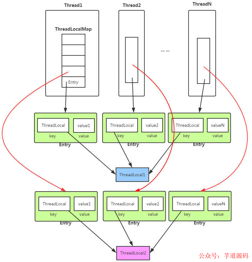
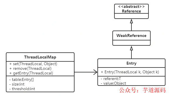
") ThreadLocal是什么
ThreadLocal是什么


 工商網(wǎng)監(jiān)
評(píng)論