 電子發燒友App


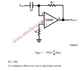
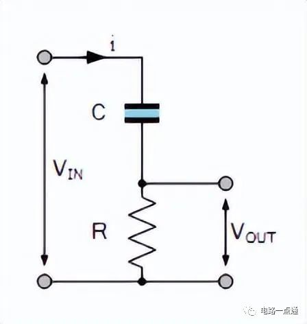
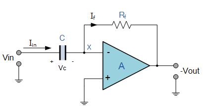
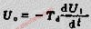
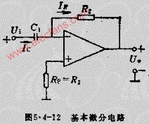
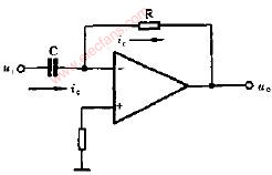
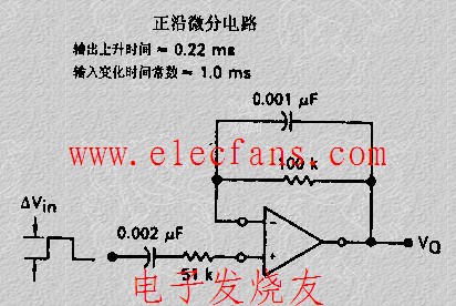
The differentiator is shown in Figure 6 and, as the name implies, is used to perform the mathematical operation of differentiation. The form shown is not the practical form, it is a true differentiator and is extremely susceptible to high frequency noise since AC gain increases at the rate of 6 dB per octave. In addition, the feedback network of the differentiator, R1C1, is an RC low pass filter which contributes 90° phase shift to the loop and may cause stability problems even with an amplifier which is compensated for unity gain.
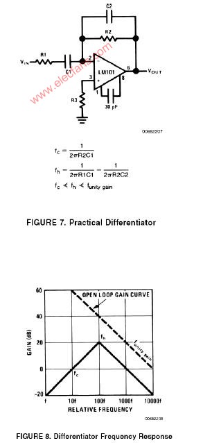
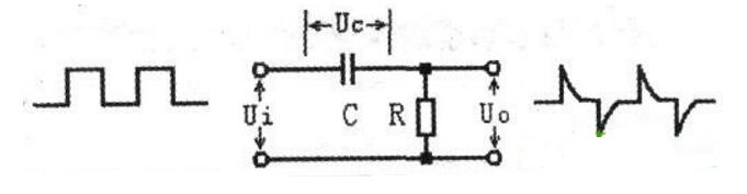
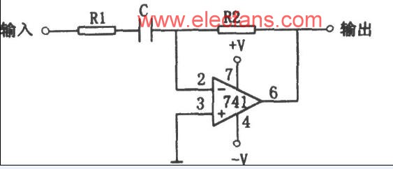
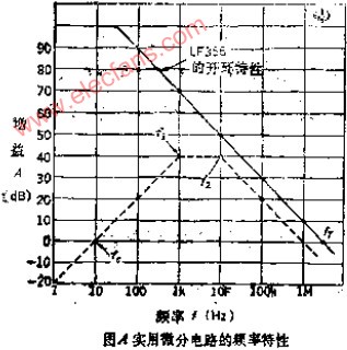
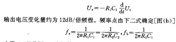
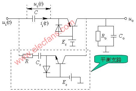
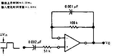
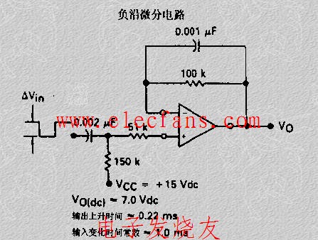
A practical differentiator is shown in Figure 7. Here both the stability and noise problems are corrected by addition of two additional components, R1 and C2. R2 and C2 form a 6 dB per octave high frequency roll-off in the feedback network and R1C1 form a 6 dB per octave roll-off network in the input network for a total high frequency roll-off of 12 dB per octave to reduce the effect of high frequency input and amplifier noise. In addition R1C1 and R2C2 form lead networks in the feedback loop which, if placed below the amplifier unity gain frequency, provide 90° phase lead to compensate the 90° phase lag of R2C1 and prevent loop instability. A gain frequency plot is shown in Figure 8 for clarity.
微分器的電路如圖6,其用于實現數學上的微分運算。這里給出的電路形式不是實際的應用形式。由于其6dB/2倍頻程的交流增益特性,其對高頻噪聲將相當敏感。反饋環路中,R1C1組成了一個等效的低通濾波器,由于其在反饋環中90°的相移,即使對單位增益采取了補償措施,在這里也可能出現穩定性問題。
圖7為微分器的實際應用電路。這個電路考慮了穩定性因素和噪聲因素,增加了R1和C2。R2-C2在反饋環路上構成了一個6dB/2倍頻程的高頻衰減網絡,R1-C1在輸入上構成了一個6dB/2倍頻程衰減網絡,這樣,整個頻率特性呈現為12dB/2倍頻程的高頻衰減,抑制了由于高頻信號輸入OP所帶來的噪聲。R1C1、R2C2一同在反饋環路上構成了一個網絡,如果將其頻點設置在OP的單位增益帶寬之內,其將提供90°前向相移,以補償由R2-C1帶來的90°相位滯后,提高環路的穩定性。波特圖如圖8所示。


 工商網監
工商網監
評論